Making the
Temperature Bar gauge working on a SIP Tacho (MV914XXXJ) on GTS Facelift
125-300 '14->
If you use the new 2016 SIP Digital Tacho on a facelift Vespa
GTS (2014 and newer), the temperature Bar gauge in the bottom left-hand corner
is not working. This is as designed, but in fact pretty sad because with a few
changes, we can make it work. And it looks cool. The trick is this: The facelift
GTS has standard two NTC's build in the coolant temperature sensor. But only
one is used. To make the Temperature Bar working, we will simply need to use
the second NTC and connect that with the SIP Tacho.
You need to do 3 things:
1) Modify the connector on the temperature sensor
2) Modify the connector to the SIP tacho
3) Pull a wire from temperature sensor at the engine to the
tacho
This is what we need to achieve:
Material
needed:
1) 1 Flat
AIV Kontakte für Mini ISO-Gehäuse 0.5-1mm2 (Conrad article 742966)
2) 1
Steckschuh Kontakt (Conrad article 526164)
3) 2 meter
automotive cable 1 mm2
4) 50 cm 3mm tubing (‘Schrumpfschlauch')
5) A few tie wraps
6) A multimeter (for testing the contacts, measuring
resistance)
7) A few drops of glue
Modify the temperature connector
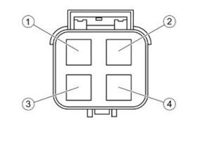
The green temperature sensor in the engine has 4 flat pins.
Each pair is connected to an NTC. Per default, only pin 1-2 are used for the
temperature warning light. Pin 3-4 are connected to the second identical NTC. Both NTC's are identical. We will need to connect pin 3-4.
![]()
Pry-off the green connector from the sensor. Open the
connector at the back (cable side).
Remove the two dummy pins from the connector. You don’t need them.
Make two wires (1mm2) and solder a wire to an AIV Flat Female
Kontakt pin 0.5-1mm2). Conrad article 742966.
Shift the black rubber shoe back from the temperature
connector. Pry-off the little yellow plate from the connector. Now, take the
two wires and shift them into the empty holes in the connector from the bottom
(not the cable side). Make sure they are aligned with the direction of the flat
pins in the sensor. Ensure that the kontakt pins just reach the bottom of the
connector. Place the yellow plate back.
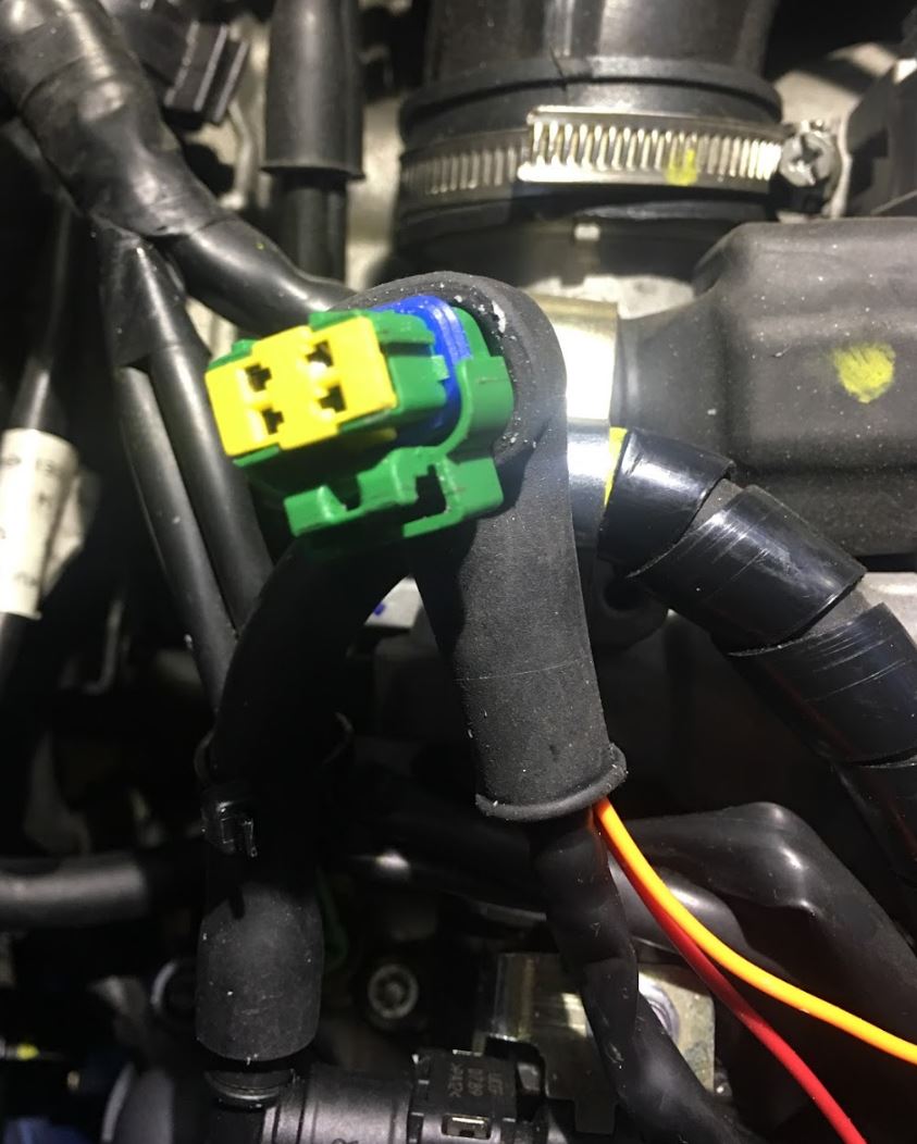
On the top of the connector, you have now the standard black
cable and your two new wires sticking out of the connector, red and yellow on
the picture.
Carefully hold the two wires and the plug and
reattach it to the sensor on the engine. Don't use force.
Test if it works: measure the resistance between the two
wires. It should read anywhere between 2000 and 5000Ω. If you have that, it means that the
new pins in the plug are properly connected with the NTC in the sensor. If your
Ohm-meter reads ‘infinite', it means that the two new wires are not properly
connected and you need to recheck your plug-fix. One of the pins may be
damaged.
You will see that the new wires may be a little loose. I put a few
drops of glue into the back of the connector with the two new wires to secure
them. Refit the rubber shoe to the back of the connector.
Modify the Plug on wire harness from the SIP Tacho
We
need to use pin 17. The number is clearly marked on the plug in the standard
wire harness from SIP, this connection has no barrel pin in the plug, so we
need to add a barrel pin to the plug.

For
the new barrel pin, we use a standard round micro female ‘Steckschuh'. Conrad
artikel nr. 526164.
Solder
a wire (1mm2) to the barrel pin.
Shift the new wire with barrel pin into the number 17 hole from
the cable side of the Tacho plug.
If the hole is too tight, use us 2.5mm drill and widen the number
17 hole a little bit so the pin with wire fits into the plug. When properly
fitted, you will see the new barrel from the other side of the plug.
Carefully refit the connector to the back of the tacho. Don't use
excessive force.
Next steps:
Connect one of the wires from the temperature plug in the engine
to the new wire at pin 17 to the Tacho. It is not critical which wire you use,
any of both pins work.
Lead the wire through the opening on the engine side from the
battery compartment. You probably need to remove the back plate of the glove
box etc., otherwise you can't get the wire through the inner guts of the
scooter. It is a good idea to use extra tubing (‘schrumpfschlauch') on the wire
in the engine compartment to protect against heat. Fix the wire here and there
with tie-wraps.
Connect
the other wire from the temperature connector to a ground point in the engine
room using a ring crimp. I used one of the screws. Not critical which one you
use, as long as it is a good ground connection.
The
sensor is now connected to the tacho.
Test
it, and switch on the ignition. Presto…!! You will have now the beautiful
temperature gauge on the SIP tacho working for your 2014-15-16-17 GTS…

The standard temperature is 3 bars, at least on my 2015 GTS.
In the SIP Tacho setup menu you can define at how many bars the
alarm will go off.
PDF:
https://drive.google.com/open?id=0ByfEwG8NFrnpQzU2V3FMVnMwZ1E